

signal integrity maintained in flex circuit designs
High-speed electronic signals require a highly efficient, low-loss transmission path to deliver maximum performance. The key to preserving signal integrity is maintaining controlled impedance, a process that requires careful attention to design and fabrication to avoid unwanted signal degradation or distortion. When this crucial principle is violated, electronic devices and components can malfunction or fail to function as intended.
High frequency circuits can introduce a number of significant signal integrity challenges that are difficult to mitigate, including signal loss, delay variations, and jitter. When these issues are not addressed during the design and manufacturing process, they can result in costly rework or product failures.
In order to maintain signal integrity at higher frequencies, it is important to use the right materials, minimize impedance discontinuities, and optimize signal routing in flex circuit designs. Taking these steps can help ensure that high-speed electronics operate properly and meet regulatory compliance requirements.
How is signal integrity maintained in flex circuit designs
Printed circuit boards (PCBs) are essential to virtually all modern electronic devices and components. They serve as the platform that enables devices to perform vital functions, from transmitting data and processing information to providing power and connectivity to external components. In addition, advancements in PCB technology continue to accelerate, making smaller and more complex flex circuits possible for a variety of applications.
As PCB technology continues to evolve, high-speed flex circuits are becoming increasingly common for various industries. But, in order to achieve the performance demanded by these new applications, it’s critical to address signal integrity challenges that arise as a result of their unique construction and layouts.
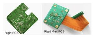
Achieving robust signal integrity in flex and rigid-flex PCBs demands meticulous attention to detail throughout the design and manufacturing process. In this blog post, we will explore the intricacies of designing for controlled impedance in flex circuits, and discuss the factors that impact the ability to maintain signal quality at high speeds.
To achieve proper signal transmission and avoid signal attenuation, flex circuits must utilize a low-loss substrate material with an appropriate dielectric constant. Choosing the right materials can also help reduce signal delays and improve overall system performance.
Using high-quality copper foil that has uniform thickness and low surface roughness is important to achieving consistent impedance across the entire flex circuit. It’s also necessary to monitor and control the copper foil thickness during manufacturing to ensure it meets required tolerances.
In addition, addressing the mechanical durability of flex circuits requires careful consideration for factors like bend radius compliance, material fatigue resistance, and stress distribution throughout different operational scenarios. This optimization can facilitate rigid-flex stackups that are capable of withstanding high-speed signal transmission while remaining mechanically reliable.
During the design phase, utilizing electromagnetic simulation tools can provide insights into signal propagation and impedance profiles, helping to identify potential sensitivity issues before they are encountered in the production process. Through this iterative process, engineers can maximize rigid-flex PCB reliability and performance while maintaining the highest levels of signal integrity. Combined with prototyping and rigorous testing, this iterative design process can help ensure that high-speed flex circuits achieve the performance standards and regulatory compliance required by their industry.


